FlexAFM and nanomotion sensing unveil cellular responses, offering new insights into bacterial behavior and potential ...

23.02.2024

Héctor here, your AFM expert at Nanosurf calling out for people to share their Friday afternoon experiments. Today I dig even deeper onto simulating AFM behaviour using Unity physics engine and introducing cantilever bending and laser readout.
In 1928, René Magritte revealed this:
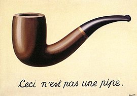
Meaning that this is not a pipe, it is a representation of a pipe. Going even deeper, pictures, drawings, holograms of a pipe will not be the pipe. Invert the colors, change its shape, it will still be the representation of a pipe, but not a pipe. Even when you hold a pipe in your hands, that is not a pipe, it is the stimulus we perceibe as a pipe. Then... what is a pipe? A pipe is an idea, it doesn't exist, at best we can get representations or signals that come to our senses and we asociate them with the pipe idea.
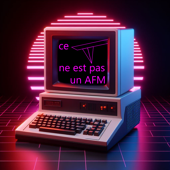
In a similar way, this is not an AFM:

This is a representation of an AFM that keeps some of the fundamental properties of an AFM, and we hope that these are suficient to learn something new that also applies to the real AFM.
Last week I presented you a simulation of an AFM made in Unity. It just had the geometry of the AFM, none of the dynamics, and we hoped to learn about convolution. It was a simulation in the sense that the physics engine was left alone to calculate the collision point between irregular shapes.
This week, I upgraded the model to include cantilever vendeing and laser readout. The laser redout is quite similar to the real one, the physics engine calculates reflections and bends accordingly to the surface where it is being reflected. The cantilever vending was done by discretizing the cantilever onto segments that are linked together with springs. A rather basic model for the cantilever, but yet complex enough to ilustrate the bending when the AFM probe tries to indent onto a surface. With this in mind, let's judge the suitability of the model by its output and let's also compare it with the ideal one we obtained last week.

The main feature is the laser detection, which I think resembles quite well the real laser. It travels in straight line, and calculates reflections based on the normal of the surface it hits. It doesn't focus or create secondary reflections, but we can consider those laser-related artefacts and put them aside to be studied later.
The bendable cantilever, although novel of this simulation, I consider it a minor feature, because it is a basic model to accomplish bending, but I think doesn't properly represent how any silicon or metal probe bends. In other words, it is something to improve, but as a quick solution, I think it is not so bad.

One thing that this model doesn't properly captures is time. This is because of the quantization of the simulated time. Because there is a small, but finite time step, high frequency behaviour is lost in this simulation, this is why the probes look rather soft, it is simply not possible to simulate something that reacts quicker than the time steps themselves.
So... how did it work?
Not too good. First of all, the simulation now takes way too long. Part of the problem is that it takes a long time for the cantilever to settle down and after each approach curve it rings as it moves away from the surface. I tried adding drag and stiffening the springs joining the cantilever segments, but that doesn't seem to help a lot. A part from more time consuming, does this creates aditional problems? Yes it does, if the surface is too high, there isn't enough time during the retracting of the probe for it to settle down, and the deflection setpoint is triggered before reaching the surface. This can be seen on the top right of the figure above as bright points.
Next there is an issue related to the way I moved the probe. I chose to do incremental steps in-plane instead of moving to fixed positions. This should work... unless the probe is a physical object which moves slightly when colliding with objects... and unless there is a rounding error in the software (which there is). This creates the effect of drift (I think the software adjusts the rounding error dynamically, meaning that sometimes is larger than others). This can be easily corrected introducing the equivalent of a "close-loop" in-plane, but it was a problem that wasn't obvious until we did the simulation. It is interesting however, that this seems similar to drift in real AFMs. In a way, the dynamic rounding error can be considered as thermal noise.
On the positive side of things, the U-shaped artefact seen in the previous simulation is gone. This was due to software, nothing to do with probe or cantilever artefacts.
Let's recap. The AFM simulator has received an improvement adding a bendable cantilever and laser readout. This allows for a simulation closer to the reality, however, it highlighted issues on the code that weren't obvious before. Luckly, they seem easy to fix. The in-plane close loop is just a line of code, and the degrading probe can be solved by creating a new probe geometry before each approach (this will also solve the settling down issue). In principle, since probe will be re-generated for each approach, I can remove the retract step altogether and double the simulation seed, however, I think it is a nice feature keeping it as it can be used in future simulations.
I hope you find this useful, entertaining, and try it yourselves. Please let me know if you use some of this, and as usual, if you have suggestions or requests, don't hesitate to contact me (like George does). Don't forget to check out his software also.
Ah, one last thing. I not only break real probes, I also break simulated ones (it was not easy to come up with the parameters that made all of this work). By the way, it is not a joke or photoshop, the probe can really break in the simulation if enough force is applied between the linkages.

23.06.2026
FlexAFM and nanomotion sensing unveil cellular responses, offering new insights into bacterial behavior and potential ...

27.05.2026
Explore Alejandro Silhanek’s innovative spintronics research, showcasing how spin waves can be investigated leveraging ...
.jpg?width=330&height=330&length=330&upsize=true&upscale=true&name=Mayfield%20Girls-202581%20(1).jpg)
19.05.2026
A group of young girls from Mayfield school wanted to start a F24 electric car racing team, and Nanosurf decided to ...

08.12.2024
Learn how to make a Python code to interface your AFM with a gamepad.
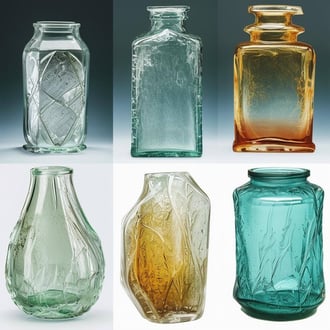
01.10.2024
Discover how different types of glass age and degrade over time, and learn how to use AFM technology to investigate ...
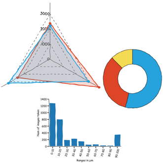
11.07.2024
FridayAFM: learn how to perform datamining on large sets of AFM data.
Interested in learning more? If you have any questions, please reach out to us, and speak to an AFM expert.