FlexAFM laser and detector alignment
Part 1: Laser-Cantilever Alignment
Step 0
The following laser-cantilever alignment steps assume that the laser is not touching any part of the cantilever or chip.
To increase the size of the laser spot, hold the AFM scan head 10-20 cm above your workbench while you follow these steps.
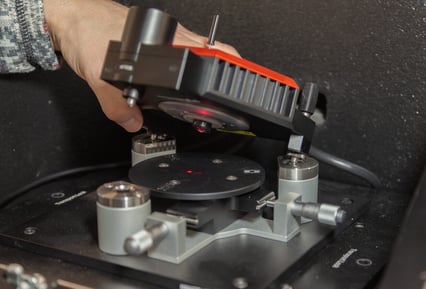

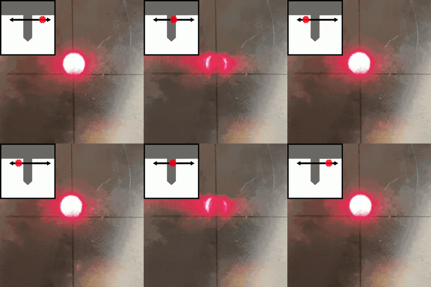
Appearance of laser spot when not on cantilever
Step 1 - Find the edge of the chip
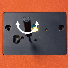
Insert the laser alignment tool (LAT) into the 4th hole and turn until the laser is blocked by the edge of the chip. Finally, move the laser so that it just re-appears past the edge of the chip.
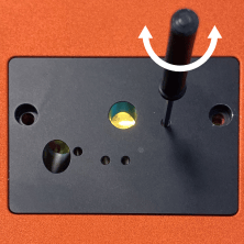
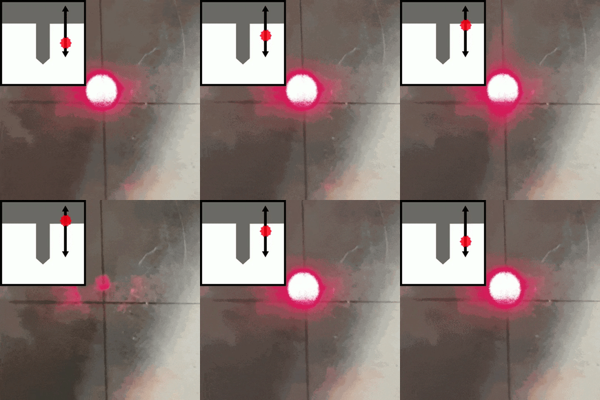
Step 2 - Find the cantilever
Insert the LAT into the 3rd hole and turn until the laser passes over the cantilever. You should see the laser spot get blocked and then reappear on the other side. Finally, move the laser back onto the cantilever so that the laser spot is blocked.
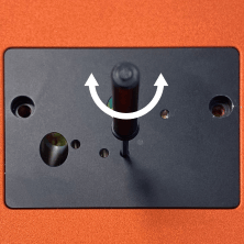
Step 3 - Move to end of cantilever
Insert the LAT back into the 4th hole and turn until the laser reaches the end of the cantilever and the laser spot gets bright again. Finally, move the laser back onto the end of the cantilever.

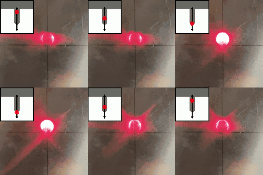
Step 4
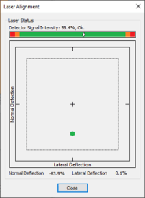
Check the Deflection Signal Intensity in the Laser Alignment Dialog. The mark should be within the green bar. Using the LAT go between the 3rd and 4th holes and try to maximize the Detector Signal Intensity.
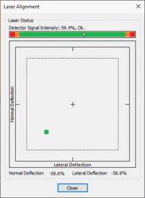
Maximized Detector Signal Intensity
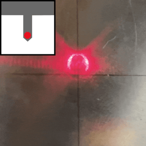
Final Position of Laser
Part 2: Detector Alignment
Step 0
After the laser is aligned to the cantilever, the next step is to align the detector to laser spot that is reflected from the cantilever. The goal is the get the laser spot, denoted by the green dot, into the center of the square. The next two steps can be done in any order.
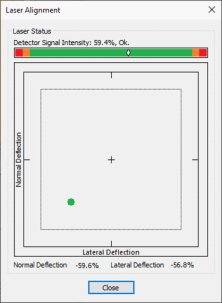
Initial Position
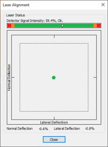
Goal
Step 1
Insert the LAT into the 1st hole and turn until you have centered the Lateral Deflection Signal.
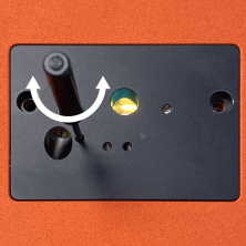

Before
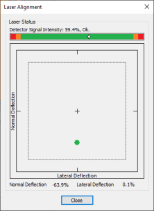
After
Step 2
Insert the LAT into the 2nd hole and turn until you have centered the Normal Deflection Signal.
Before

After
Step 3
Go between Steps 1 and 2 to fine tune the position of the detector until you are satisfied.